Chapter 4: Architecture Design
Designing comprehensive security architecture for unified network protection
4.1 Basic Network Security Architecture
The basic network security architecture provides essential protection for small to medium organizations with straightforward network topologies. This design focuses on establishing a solid security foundation with minimal complexity while ensuring comprehensive threat prevention at the network boundary.
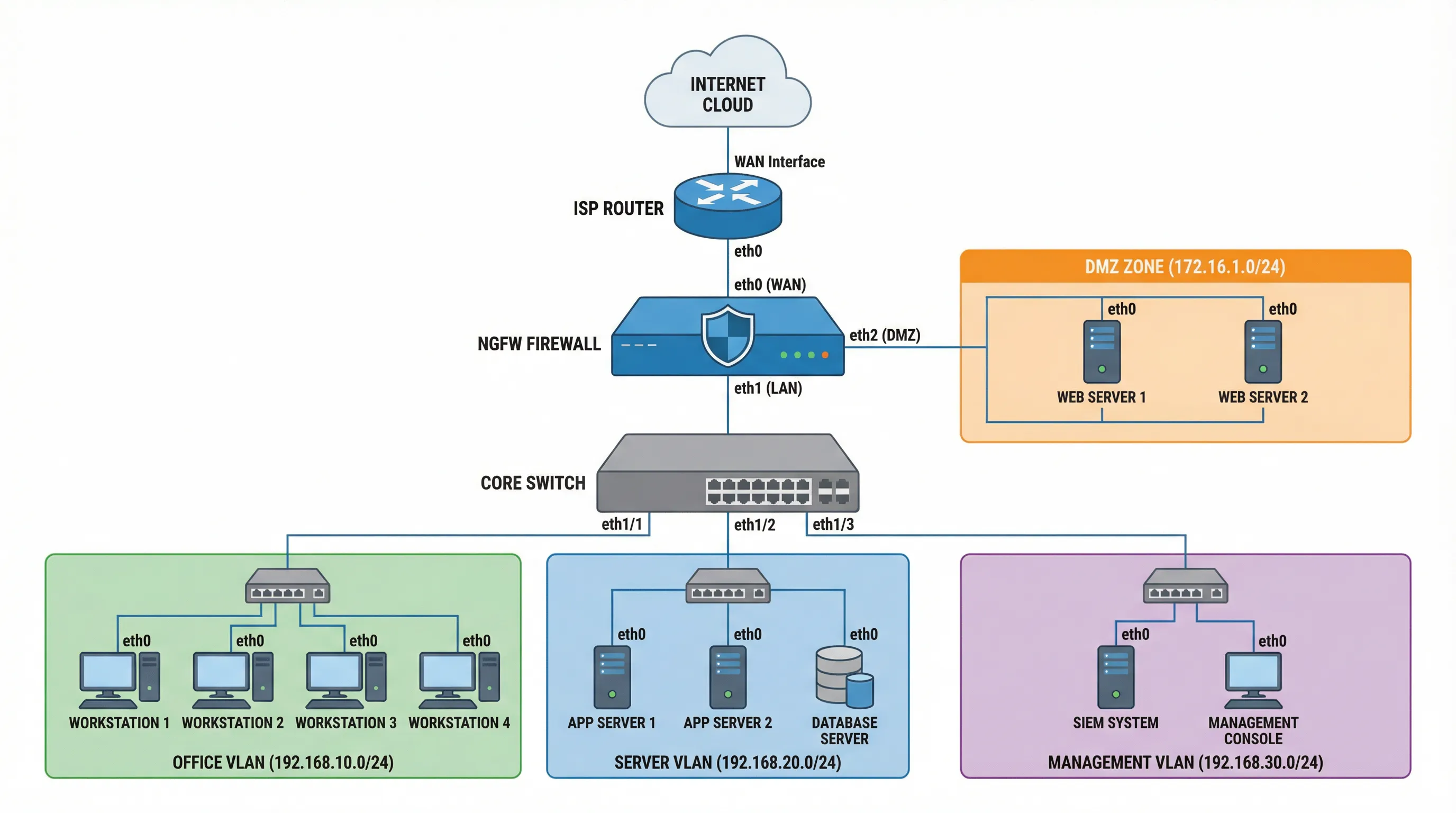
Architecture Components
The basic architecture implements a three-zone security model that separates network traffic into distinct trust levels, enabling granular security policy enforcement and reducing the attack surface.
| Zone | Purpose | Security Level | Typical Devices |
|---|---|---|---|
| WAN Zone | Internet connectivity | 0 (Untrusted) | ISP router, WAN interface |
| DMZ Zone | Public-facing services | 50 (Semi-trusted) | Web servers, mail servers, DNS |
| LAN Zone | Internal network | 100 (Trusted) | Workstations, internal servers, databases |
| Management Zone | Security management | 100 (Isolated) | SIEM, management consoles, logging servers |
Traffic Flow and Policy Enforcement
- Internet to DMZ: Allow HTTP/HTTPS with IPS inspection and application control
- Internet to LAN: Deny all inbound by default, allow VPN and specific services
- LAN to Internet: Allow with URL filtering, antivirus, and SSL inspection
- LAN to DMZ: Allow with application-level inspection
- DMZ to LAN: Deny by default, allow only specific database queries
- Management Zone: Isolated access via dedicated management interface only
Design Considerations
When implementing the basic architecture, organizations should consider network segmentation using VLANs to logically separate different departments or functions within the LAN zone. This provides an additional layer of security and enables more granular policy enforcement. The NGFW should be sized appropriately to handle peak traffic loads with all security features enabled, typically requiring 30-50% headroom above average throughput.
4.2 Advanced High-Availability Architecture
The advanced architecture is designed for enterprises requiring high availability, redundancy, and scalability. This design eliminates single points of failure and provides seamless failover capabilities to ensure business continuity.
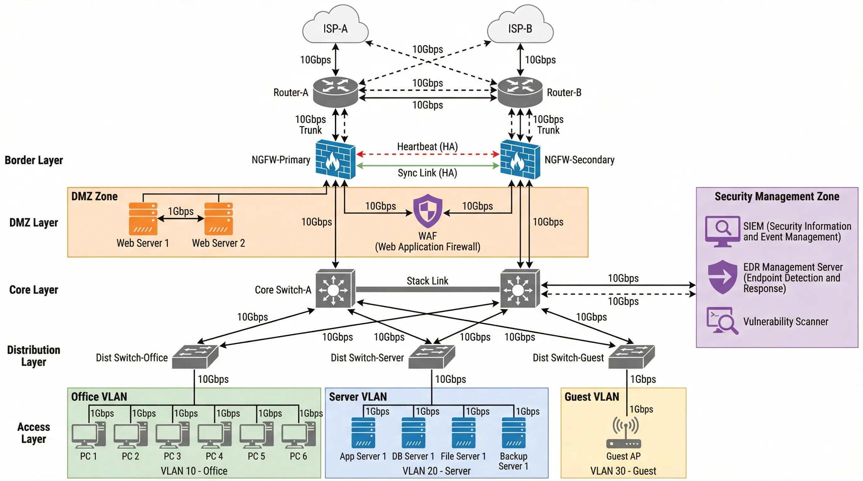
High Availability Components
| Layer | Component | Redundancy Method | Failover Time |
|---|---|---|---|
| Border Layer | Dual ISP connections | Active-Active with BGP | <1 second |
| Security Layer | NGFW cluster (Primary + Secondary) | Active-Passive with state sync | <3 seconds |
| DMZ Layer | WAF + Load balancer | Active-Active with health checks | Immediate |
| Core Layer | Dual core switches | Stack or VSS configuration | <1 second |
| Distribution Layer | Redundant uplinks | LACP link aggregation | Immediate |
NGFW High Availability Configuration
- Heartbeat Link: Dedicated connection for health monitoring between primary and secondary firewalls, typically using a direct crossover cable or dedicated VLAN
- Synchronization Link: High-speed connection for session state synchronization, ensuring seamless failover without dropping active connections
- Configuration Sync: Automatic replication of security policies, routing tables, and system configurations from primary to secondary
- Failover Triggers: Interface failure, device failure, or manual failover initiated by administrator
- Virtual IP (VIP): Shared IP address that moves between primary and secondary during failover, transparent to connected devices
Network Segmentation Strategy
The advanced architecture implements a hierarchical network design with multiple VLANs for different security zones and business functions. Office VLAN (VLAN 10) hosts user workstations with standard security policies. Server VLAN (VLAN 20) contains application servers and databases with stricter access controls. Guest VLAN (VLAN 30) provides isolated internet access for visitors without access to internal resources. Each VLAN is assigned to a dedicated distribution switch with redundant uplinks to the core layer.
Scalability Considerations
The architecture supports horizontal scaling by adding additional distribution switches and access layer devices as the organization grows. The core layer should be designed with sufficient port density and bandwidth to accommodate future expansion. NGFW clustering can be extended to active-active configuration for higher throughput, though this requires more complex configuration and licensing.
4.3 Physical Wiring and Cabling Design
Proper physical cabling is critical for reliable network security infrastructure. This section details the physical connections, cable types, and best practices for NGFW deployment.
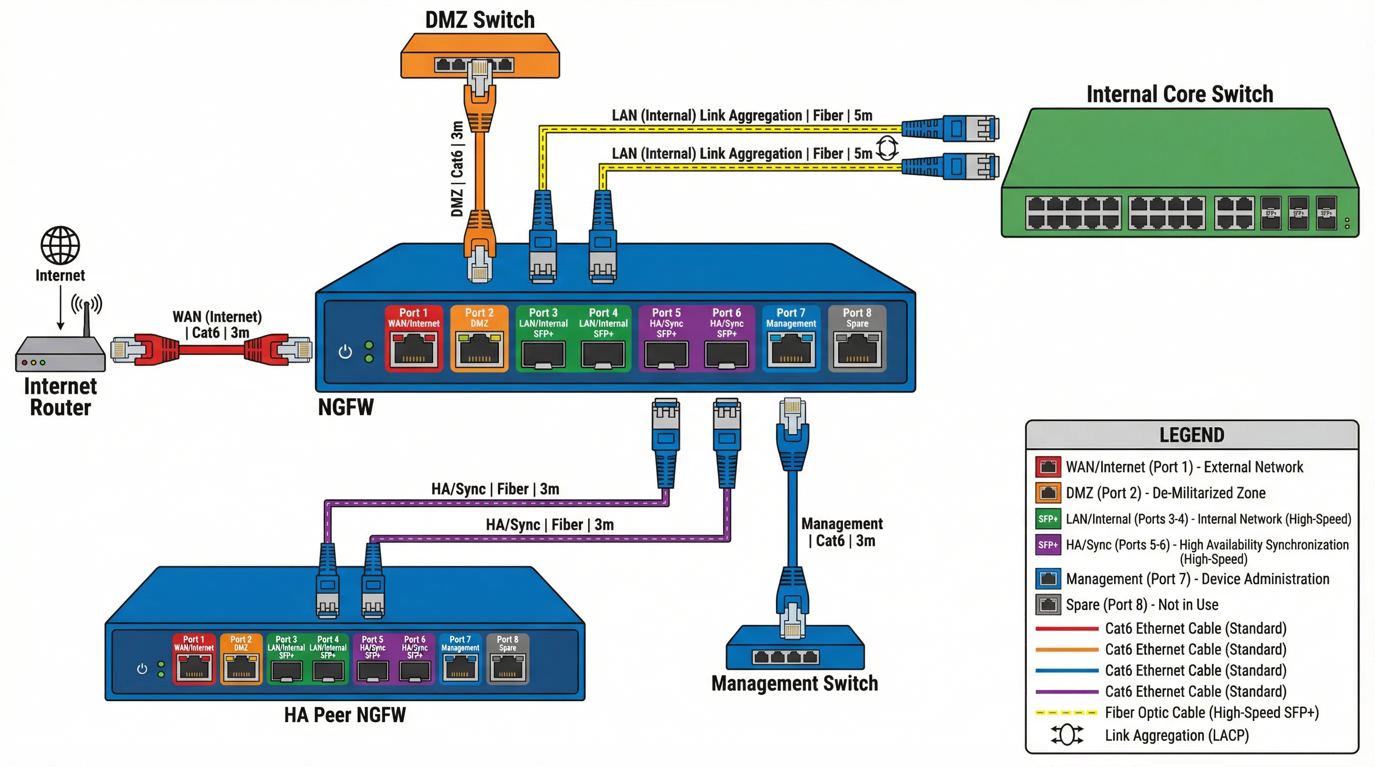
Interface Assignment and Cabling
| Port | Function | Cable Type | Speed | Connection |
|---|---|---|---|---|
| Port 1 | WAN/Internet | Cat6 UTP or Fiber SFP+ | 1Gbps - 10Gbps | ISP router or border router |
| Port 2 | DMZ | Cat6 UTP | 1Gbps | DMZ switch |
| Port 3-4 | LAN/Internal (Bonded) | Cat6 UTP or Fiber | 2Gbps - 20Gbps | Core switch (LACP) |
| Port 5-6 | HA Sync/Heartbeat | Cat6 UTP or Fiber | 1Gbps - 10Gbps | HA peer firewall |
| Port 7 | Management | Cat6 UTP | 1Gbps | Management switch |
| Port 8 | Spare | - | - | Reserved for future use |
Cable Selection Guidelines
- Cat6 UTP: Standard for 1Gbps connections up to 100 meters, suitable for most LAN and management interfaces
- Cat6A or Cat7: Required for 10Gbps over copper, recommended for high-speed core connections
- Fiber Optic (Single-mode): For long-distance connections (>100m) or inter-building links, supports 10Gbps to 100Gbps
- Fiber Optic (Multi-mode): For short-distance high-speed connections within data centers, typically OM3 or OM4
- Direct Attach Copper (DAC): For very short high-speed connections (<7m) between adjacent devices in racks
Cabling Best Practices
All cables should be clearly labeled at both ends with source and destination information, including device name, port number, and VLAN/zone assignment. Use color-coding to differentiate cable types and functions: red for WAN/Internet, orange for DMZ, green for LAN, blue for management, and purple for HA links. Maintain proper cable management with cable trays, velcro ties (not zip ties which can damage cables), and adequate slack for maintenance. Document all cable runs in a centralized cable management database with physical location, length, and installation date.
Power and Environmental Considerations
NGFW devices should be connected to redundant power sources, preferably from separate UPS units or power distribution units (PDUs). Ensure adequate cooling and airflow around the device, maintaining ambient temperature between 0-40°C (32-104°F). For high-availability deployments, primary and secondary firewalls should be powered from different electrical circuits to avoid simultaneous power failure.
4.4 Architecture Design Principles
Successful security architecture design follows fundamental principles that ensure effectiveness, maintainability, and alignment with business objectives.
Defense in Depth
Implement multiple layers of security controls rather than relying on a single perimeter defense. Each layer provides an additional barrier that attackers must overcome, significantly increasing the difficulty and time required for successful compromise. Layers include network perimeter security (NGFW), application layer protection (WAF), endpoint security (EDR), and data protection (encryption, DLP).
Least Privilege Access
Configure security policies based on the principle of least privilege, where users and systems are granted only the minimum access necessary to perform their functions. Default-deny policies should be implemented, with specific allow rules created only for legitimate business requirements. Regular access reviews should be conducted to remove unnecessary permissions.
Network Segmentation
Divide the network into smaller, isolated segments based on security requirements, business function, or data sensitivity. Segmentation limits the blast radius of security incidents and prevents lateral movement by attackers. Use VLANs, firewalls, and access control lists (ACLs) to enforce segmentation boundaries.
Monitoring and Visibility
Comprehensive logging and monitoring are essential for detecting security incidents and troubleshooting issues. All security devices should send logs to a centralized SIEM platform for correlation and analysis. Network traffic should be monitored for anomalies, and security dashboards should provide real-time visibility into threat landscape and system health.
Scalability and Future Growth
Design the architecture with growth in mind, ensuring that security infrastructure can scale to accommodate increasing traffic, users, and applications. Choose devices with sufficient capacity headroom (typically 30-50% above current requirements) and modular designs that support incremental expansion. Plan for technology refresh cycles to avoid obsolescence.